Learning by doing
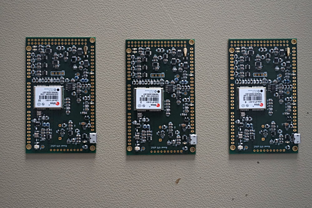
GPS Timing Shield assembled
Last week I managed to assemble 3 GPS Timing Shields in my lab. I encountered some unexpected problems with the Micro-USB connector. An excess of solder paste and/or bad aligned placement of the component caused some shorts between the pins and the case ground.
I had to remove the connector and manually solder a new component onto the PCB. This wasn’t an easy task and I cost me some hours of work and the purchase of a hot-air de-soldering station. But finally it worked out and I can connect to the GPS modul using the USB connector.
For the next version of the PCB layout I’ll improve the footprint of the connector and use a connector type with through hole ground pins for better alignment.
RUWAI